This guide will explain step by step, Ways to Write Values in OnPing using different HMI components and directly in driver configuration.
Preliminary
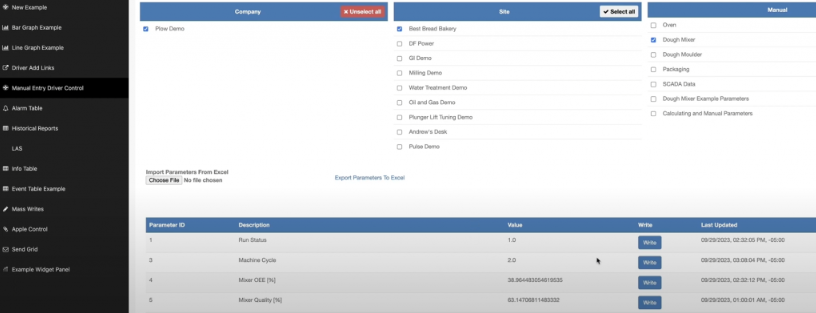
In the driver configuration, this example uses ‘Manual Entry Driver Control’. It is possible to write to parameters that have a visible ‘Write’ button in the ‘Write’ column.
Step 1: Write in driver configuration
On the driver page, when the ‘Write’ button for a parameter is selected, the corresponding Value can be updated. The ‘Write functionality’ must then be confirmed with the ‘Save’ button or discarded with ‘Cancel’.

Step 2: Write from the HMI using the Status Indicator component
In this example, the ‘New Example’ HMI is used. First, enter ‘Edit mode’ by selecting the ‘wrench’ icon in the top-right corner.

‘Edit mode’ is indicated by the feature bar being visible on top of the opened HMI screen.

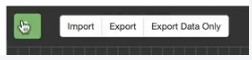
The green ‘arrow’ icon is pressed to open the component panel.
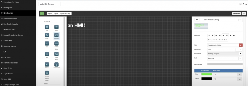
By selecting the ‘Indicator’ component, the object’s properties are visible and can be adjusted. In our example, the title is “Test Writes in OnPing”, the ‘Background’ color is adjusted to gray, and the ‘Value’ color to black.
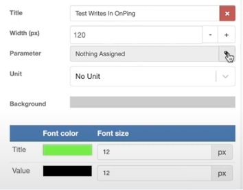
To add a parameter, select the ‘Parameter’ icon next to the field.
The required parameter must be selected. In this example, the parameter used is ‘Demo Setpoint’.

After confirmation, it will be visible in the properties of the ‘Indicator’ component.
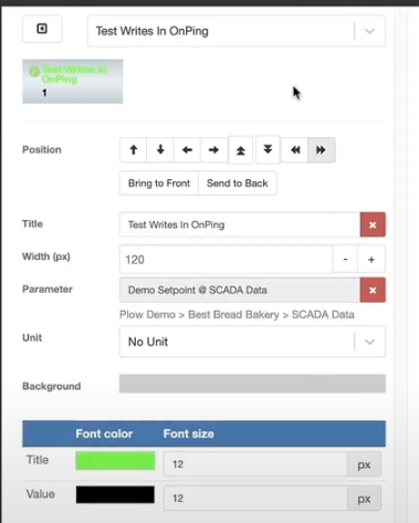
* In the example, the parameter will later be changed to ‘Example Parameter To Edit’ to stay consistent with the other methods of writing a value to a parameter.
After configuring the component, confirm it by selecting the ‘Save’ button at the bottom of the properties panel.
Then the object will be visible on the HMI and can be moved by drag and drop in the required position. After positioning it, the ‘Save Changes’ button has to be selected.
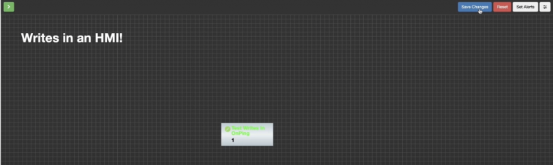
To get out of the edit mode ‘wrench’ icon has to be selected.

In the next step, select the ‘little pencil’ icon on the ‘Indicator’ component.
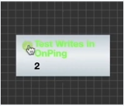
This opens a pop-up where the ‘write’ function can be performed. The pop-up description is “Test Writes In OnPing ‘Demo Setpoint’ @ SCADA Data”. “Test Writes” is what is written to the ‘Demo Setpoint’, and the location is “SCADA Data”.
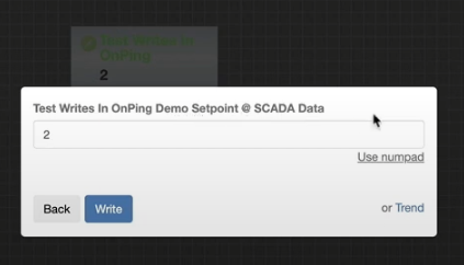
In this example, the value is changed to ‘1’ and confirmed by selecting the ‘Write’ button.
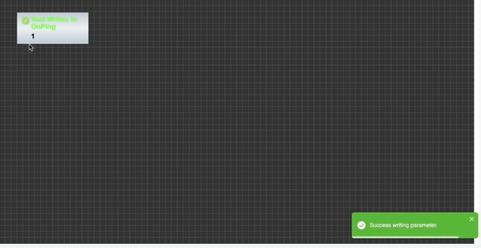
After pressing the ‘Write’ button, the pop-up disappears. At the bottom right of the screen, there is an indication that the parameter write was successful, and the value on the Indicator component has updated to ‘1’.
The other possibility, instead of typing in the value from the keyboard, is to use a number pad.
It is accessible in the pop-up when the ‘Indicator’ component is selected.
After selecting “Use numpad,” it will appear, and the desired value can be selected.
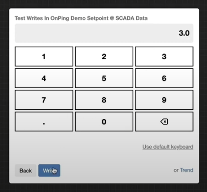
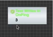
Click ‘Write’ and that changes the value, in the presented example, it is 3.
Step 3: Write from the HMI using the Table Component
Another way to write value in OnPing is through the Table component. To add another component to the HMI enter the ‘Edit mode’ by selecting the ‘wrench’ icon in the top right corner.
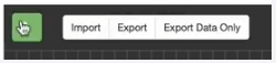
The green ‘arrow’ icon is pressed to open the component panel.
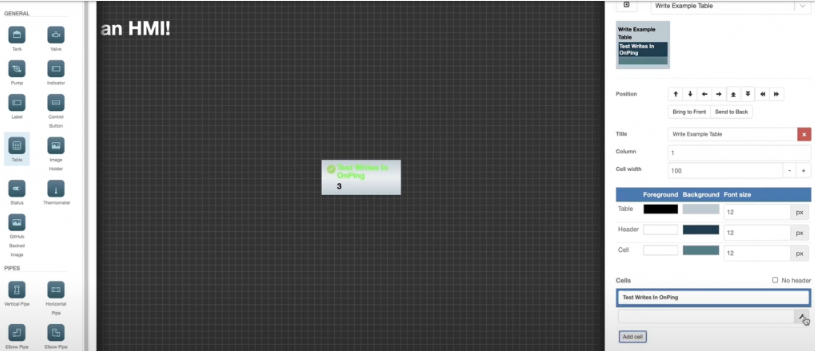
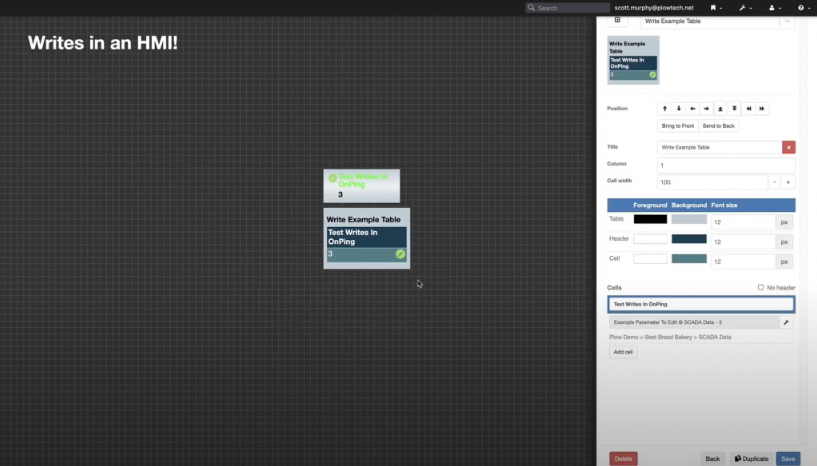
By selecting the ‘Table’ component, the object’s properties are visible and can be adjusted. In our example, the title is “Write Example Table”, the Column number is ‘1’ and the “Test Writes in OnPing” Cell is added. Select the ‘wrench’ icon to add a new parameter to the cell configuration.
In this example, the used parameter is ‘Example Parameter To Edit’.
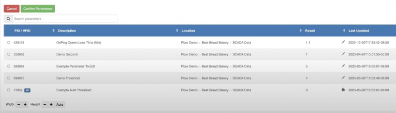
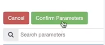
It has to be confirmed by selecting the ‘Confirm Parameters’ button.
After the configuration of the component is finished, it must be confirmed by selecting the ‘Save’ button at the bottom of the properties panel.
Then the object will be visible on the HMI in the top-left corner and can be moved by drag-and-drop to the required position.
After positioning it, the ‘Save Changes’ button must be selected.
To get out of the edit mode ‘wrench’ icon has to be selected.

Edit HMI features are no longer visible. In the next step, select the ‘little pencil’ icon on the ‘Table’ component.
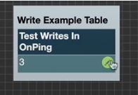
The control popup is the same as it was for the ‘Indicator’ component.
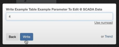
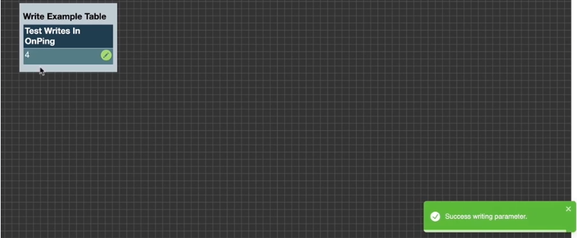
After pressing the ‘Write’ button, the pop-up disappears. At the bottom right of the screen, there is an indication that the parameter write was successful, and the value on the ‘Table’ component has updated to ‘4’.
Step 4: Write from the HMI using the Control Button component
Another way to write a value in OnPing is through the ‘Control Button’ component. It is a bit different from previous components because the numeric value cannot be entered directly. Instead, a button with defined functionality is created. To add another component to the HMI, enter ‘Edit mode’ by selecting the ‘wrench’ icon in the top right corner.
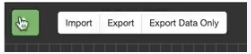
The green ‘arrow’ icon is pressed to open the component panel.
By selecting the ‘Control Button’ component, the object’s properties are visible and can be adjusted.
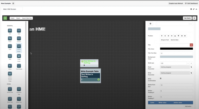
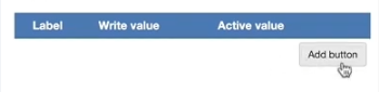
In our example, the three buttons are added by selecting the ‘Add button’.
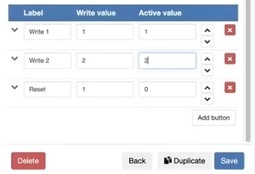
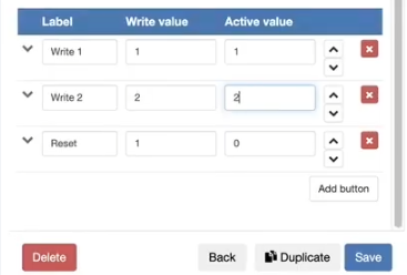
Three buttons were configured: “Write 1”, “Write 2”, and “Reset”. The ‘Write Value’ defines the value that will be written to the parameter when the corresponding button is clicked. The ‘Active value’ indicates whether the button is active, based on the defined parameter.
In our example, the title is “Test Writes In OnPing”, the Width (px) is ‘160’ and the ‘Read Parameter’, and the ‘Write Parameter’ are defined as ‘Example Parameter To Edit’. The parameters are configured in the same way as for the other objects. Notice that ‘Read Parameter’, and ‘Write Parameter’ can be different, but in this example, the same parameter is used for both properties.
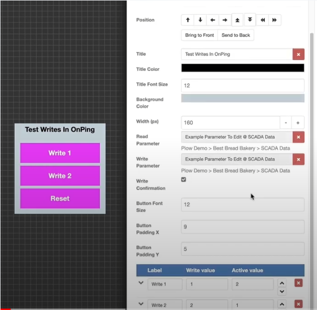
After the component configuration is complete, it must be confirmed by selecting the ‘Save’ button at the bottom of the properties panel.

To get out of the edit mode ‘wrench’ icon has to be selected.
None of the buttons is active, but all of them are writable. The current value of the parameter is “5,” which means that no ‘Active Value’ condition for any button is met.
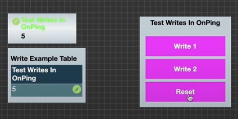
In the first step, select the ‘Reset’ button. The control pop-up indicates that the ‘Example Parameter’ value will be overwritten with ‘1’.
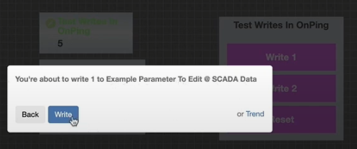
After confirmation, the ‘Write 1’ button on the HMI becomes active based on the defined ‘Active Value’.
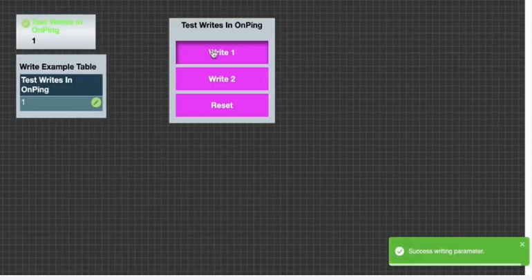
In the next step, select the ‘Write 2’ button.
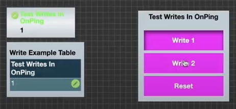
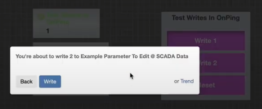
The control pop-up indicates that the ‘Example Parameter’ value will be overwritten with ‘2’.
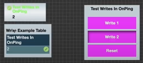
After confirmation, the ‘Write 2’ button on the HMI becomes active based on the defined ‘Active Value’. The current parameter value is visible on the previously created ‘Indicator’ and ‘Table’ components.
In the next step, select the ‘Write 1’ button.
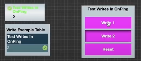
The control pop-up indicates that the ‘Example Parameter’ value will be overwritten with ‘1’.
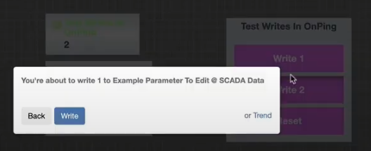
After confirmation, the ‘Write 1’ button on the HMI becomes active based on the defined ‘Active Value’. It is possible to turn off this notification.
To turn off the specified notification, the component’s configuration must be adjusted. These actions must be performed in the ‘Edit’ mode. The ‘Write confirmation’ property must be disabled.
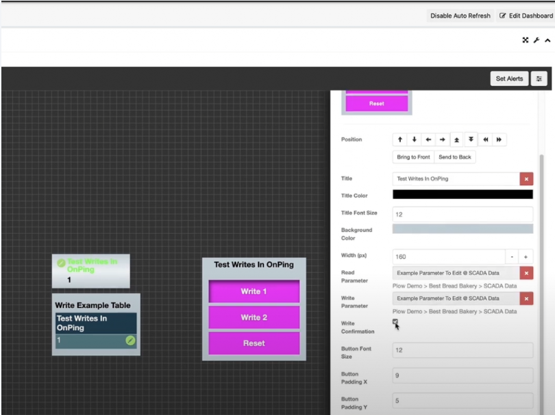
After the component configuration is complete, it must be confirmed by selecting the ‘Save’ button at the bottom of the properties panel. Note that no confirmation is required when any of the ‘Control Buttons’ is pressed; the value will be written immediately.
After disabling the ‘Edit Mode,’ the value changes whenever the button is pressed, without the need for confirmation. In the example, the ‘Write 2’ button is selected.
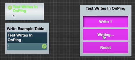
The value has changed to ‘2’.
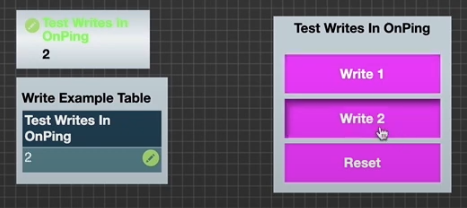
The button controls have additional functions that will be described next. For instance, the buttons can change color depending on their write state. In the ‘Edit Mode’ with the ‘Control Button’ component selected, the properties panel under the buttons section includes a cardinal that, when clicked, expands the button color properties.
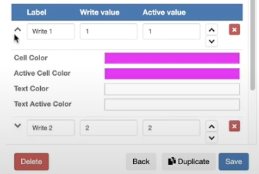
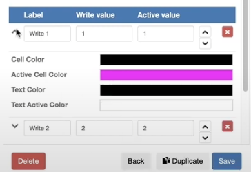
In the following example, the active ‘Cell Color’ and ‘Text Color’ are set to black for all of the buttons.
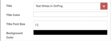
The ‘Background Color’ has been changed to black and the ‘Title Color’ to white.
After the component configuration is updated, it must be confirmed by selecting the ‘Save’ button at the bottom of the properties panel.
In the next step, the grid configuration is updated. To open the grid configuration, select the ‘menu’ icon in the top-right corner of the HMI screen.
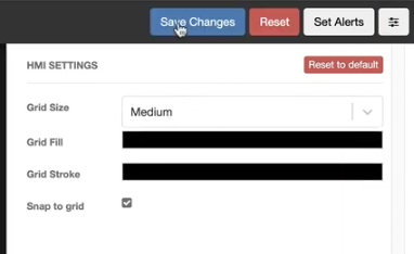
‘Grid Fill’ and ‘Grid Stroke’ are set to black. The configuration must be confirmed with the ‘Save Changes’ button.
To make the button’s functionality disappear when it is pressed, the ‘Active Value’ configuration in the ‘Control Button’ properties must be updated as shown on the attached screen.
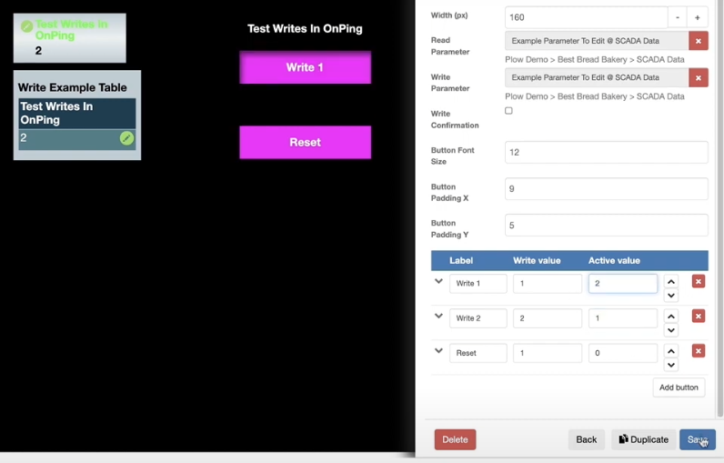
In the following functionality, whenever the button is selected, it will disappear from the screen. In the example, the ‘Write 2’ button is not visible, and the ‘Write 1’ button is pressed.
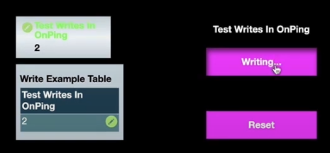
After the value has been updated, the ‘Write 1’ button is no longer visible. The ‘Write 2’ button is tested next.
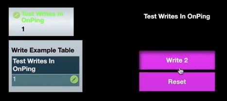
After the value has been updated, the ‘Write 2’ button disappears.

This functionality resembles the ‘On’ and ‘Off’ buttons. The button text is updated to ‘On’ and ‘Off’, and the corresponding ‘Active Cell Color’ is updated to green and red, respectively.
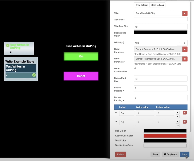
In the following example, the ‘On’ button is pressed.
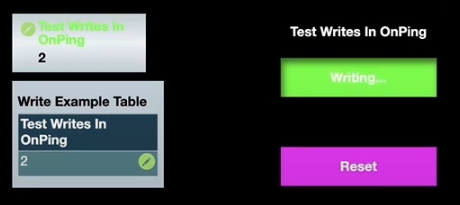
When the ‘On’ button is pressed, the parameter value will change to ‘1’. The ‘On’ button will no longer be visible, and the ‘Off’ button will appear.
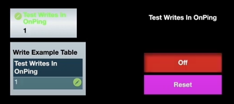
Similarly, when the ‘Off’ button is selected.
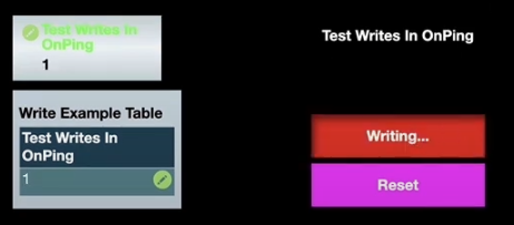
Then the parameter value updates to ‘2’ and the ‘Off’ button disappears. In the following example, the ‘Reset’ button is pressed.
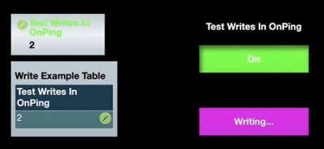
When the ‘Reset’ button is pressed, the parameter value will change to ‘1’. The ‘On’ button will no longer be visible, and the ‘Off’ button will appear.
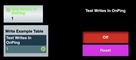
That’s an example of how the properties of the ‘Button Control’ component can be utilized in the HMI configuration.
Step 5: Write from the HMI using the Custom Table component
There is one more way to write, and that’s from a custom table. In the example, a custom table is already configured and accessible from “Info Table”.
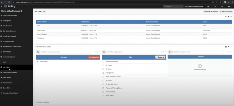
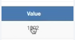
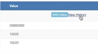
When the value in the “Info Table” is selected, the options ‘Write Value’ and ‘View History’ appear.
By selecting the ‘View History’ button, the trend for the value will be displayed.
It is possible to do a ‘Write Value’ from here and change the value of the parameter.
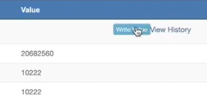
When selected, the value window becomes interactive, allowing the entry of the desired value and confirmation with the ‘Write’ button or decline with the ‘Cancel’ button.
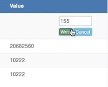
When selecting ‘Write,’ the value is updated.
Was this article helpful?
That’s Great!
Thank you for your feedback
Sorry! We couldn't be helpful
Thank you for your feedback
Feedback sent
We appreciate your effort and will try to fix the article